
It has a curve, a scheduled operating point and a motor with enough horsepower. So when TAB measures less air than the schedule calls for, the fan is usually where the finger lands first.
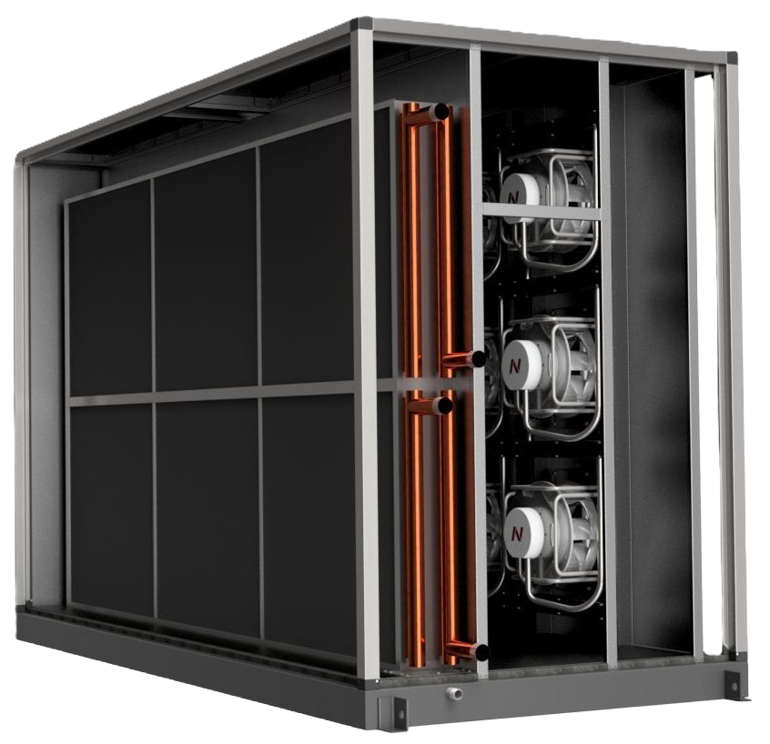
Sometimes it deserves the blame. Often, though, the fan is doing exactly what the system allows it to do.
The installed fan has to contend with the AHU and duct system actually built around it: coils, filters, dampers, transitions, elbows, plenums and whatever happened between the mechanical plans and the sheet metal going into the building.
None of those things has to be dramatically wrong to matter.
If an AHU was scheduled for 20,000 cfm and TAB can only find 18,000, the useful question is not simply:
It’s:
That question gets at something larger than troubleshooting. It gets at the difference between fan and coil selection that simply meets a schedule and engineering an airside system to perform in a building.
Two air handlers can satisfy the same airflow and cooling-capacity requirements on paper and still behave very differently once they’re operating. — One may spend much of its life comfortably at part load. Another may require more fan energy to overcome pressure losses. One coil may give the designer plenty of room for dehumidification and control. Another may meet capacity while leaving less margin when conditions change.
Both selections can be correct.
They are not necessarily equivalent.
Most fan selections begin with required airflow and static pressure.
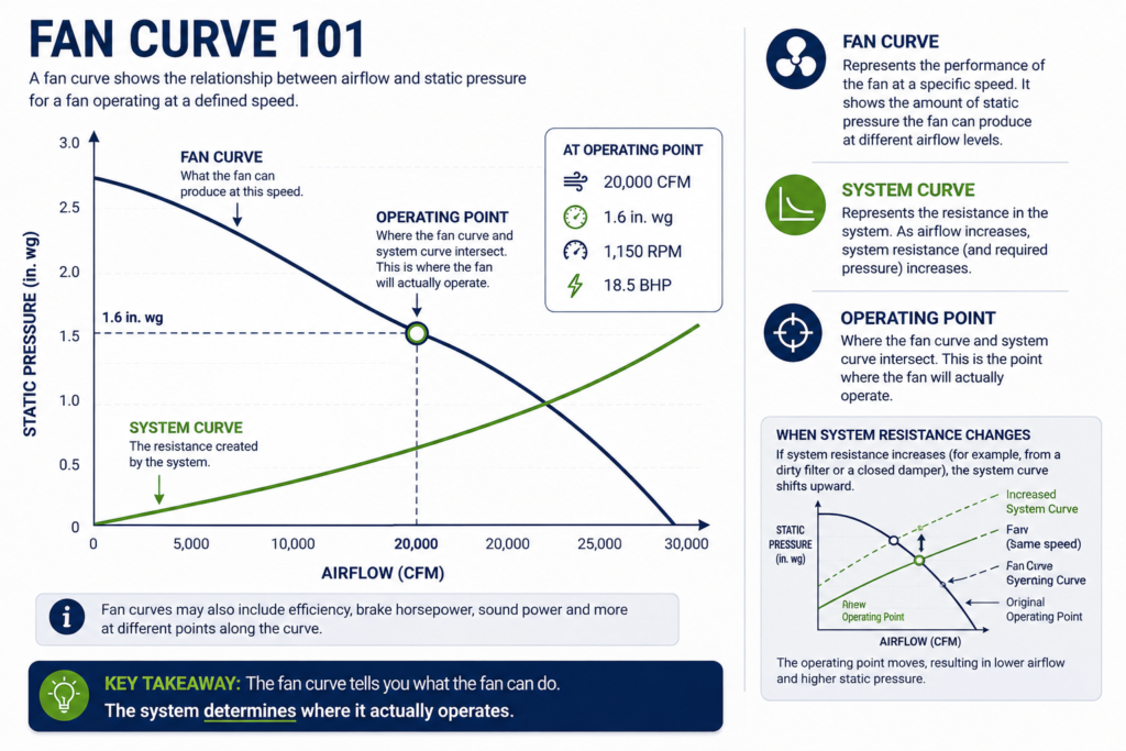
Those two conditions establish an operating point on the fan curve — but the fan doesn’t operate independently of the system connected to it.
Loads rise and fall. VAV boxes modulate. Outdoor-air quantities change. Filters load. Economizers open and close. Spaces get used differently than anticipated. As airflow requirements and system resistance change, the fan’s operating point can change with them.
That makes understanding the fan curve important beyond the initial selection.
Air leakage, pressure drop, component selection and installation conditions all influence how the airside system ultimately performs.
There is another consideration behind that curve.
Fans are rated under standardized test conditions in controlled test labs. The installed conditions aren’t always as cooperative.
An elbow close to the inlet, an abrupt transition, limited straight duct or an unfavorable discharge arrangement can affect performance. Even fan rotation relative to the first duct turn can matter.
These installation-related losses are commonly referred to as system effect.
The fan curve isn’t wrong. The fan simply may not be operating under the same conditions used to establish its published performance.
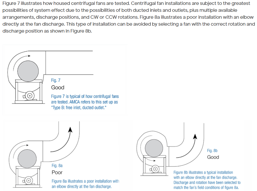
Image Credit: https://www.greenheck.com/resources/blog/understanding-fan-system-effects
Published fan performance assumes standardized test conditions. Installed inlet and discharge conditions can affect actual performance.
The typical field response is understandable, but that is why an airflow problem shouldn’t automatically lead to one response:
Increase the speed.
Sometimes increasing fan speed is exactly what needs to happen. It just shouldn’t be automatic.
The fan laws show why:
A 10% increase in fan speed theoretically increases airflow by about 10%, pressure by about 21% and power by about 33%.
That creates two questions:
Where did the additional pressure requirement come from?
And:
Can the motor handle the additional brake horsepower?
A motor selected closely around the original operating point may not have enough capacity for the additional load.
Before adding speed, it’s worth understanding what changed in the system — and whether the fan and motor can support the new operating point.
And one of the first places worth looking is sitting upstream or downstream of the fan.
Cooling coils tend to be judged first by capacity.
Can the coil meet the sensible and latent load at the scheduled conditions?
It has to.
But the first coil selection that meets capacity isn’t necessarily the right selection for the unit.
During AHU selection, each internal component contributes to the unit’s total pressure requirement. Filters, dampers, coils and other components are configured before the final fan selection is validated.
That means changing the coil can change the fan selection.
A coil may meet capacity but carry more airside pressure drop than another option. A larger coil face may reduce face velocity and pressure drop, but require a larger casing and more first cost. Additional rows may provide more heat-transfer surface while also affecting pressure drop and access for cleaning.
This is where “meets capacity” stops being enough.
Face Velocity = Airflow ÷ Coil Face Area For the same CFM, a larger coil face means lower face velocity. That can reduce airside pressure drop and help reduce the potential for moisture carryover from a wet cooling coil — but it can also increase AHU size and first cost.
Then there’s the coil five years from now.
Can it be accessed? Can it be cleaned? What happens to pressure drop when the coil and filters no longer look the way they did on startup day?
Those aren’t just maintenance questions.
They’re performance questions.
Capacity tells us whether the coil can meet the load. Face velocity, geometry, pressure drop, controllability and serviceability help determine how well the system performs while doing it.
The best-performing fan or coil isn’t necessarily the one with the highest efficiency. It’s the one that best supports the way the building will actually operate.
There is rarely one “correct” selection.
A hospital may place a premium on humidity control, redundancy and reliability. An office building may prioritize energy performance. Another project may be constrained by footprint, acoustics or first cost.
The goal isn’t to maximize every variable.
It’s to understand which compromises the project is making — and why.
Energy, humidity control, acoustics, redundancy, first cost, serviceability, controls and lifecycle performance all influence what better means for a particular application.
That is what turns equipment selection into engineering.
Once the AHU starts, the controls system works with the machine that was selected and installed.
It can’t remove pressure drop from a coil. It can’t correct poor fan inlet or discharge conditions. It can’t manufacture fan capacity that isn’t there.
But controls can have an enormous influence on how the available capacity is used.
Consider duct static pressure in a VAV system.
A fixed static-pressure setpoint can ask the supply fan to maintain pressure even when downstream demand has fallen. The VFD makes the pressure. The VAV dampers throttle it away.
Static-pressure reset allows the target to respond to actual system demand.
The question becomes:
How much pressure does the building actually need right now?
The same principle applies to coil control. A coil that satisfies a peak-load calculation still has to be controllable as airflow, water conditions and load change.
Selection establishes the operating envelope. Controls determine how intelligently the system moves within it.
None of this means the fan gets a free pass.
If an AHU is short on air, actual fan speed should be compared with commanded speed. Rotation, VFD limits, fan-array operation, motor capability, wheel condition and the measured operating point all deserve verification.
The difference is that by then, we know more.
We know the pressure drop across the filters and coil. We know something about system resistance. We know whether the fan is seeing reasonable inlet and outlet conditions. We know what static pressure the controls are asking it to maintain.
Now, if the fan cannot make the duty, we can say so for a reason.
Schedules give us a common basis for selection.
Buildings are less cooperative.
Filters load. Dampers actuate. Coils get wet and dirty. Loads change. Components need maintenance. Controls respond to what is happening throughout the system.
That is why the best-performing fan or coil isn’t necessarily the one with the most impressive number on a selection report.
It’s the one that best supports the way the building needs to operate.
Sometimes the consequences of those choices don’t become obvious until TAB is standing in the mechanical room looking for 2,000 missing cfm.
By then, the question is no longer whether the schedule was right.
It’s whether the entire airside system had what it needed to succeed from the start.
And that’s a much easier question to answer during selection than during TAB.
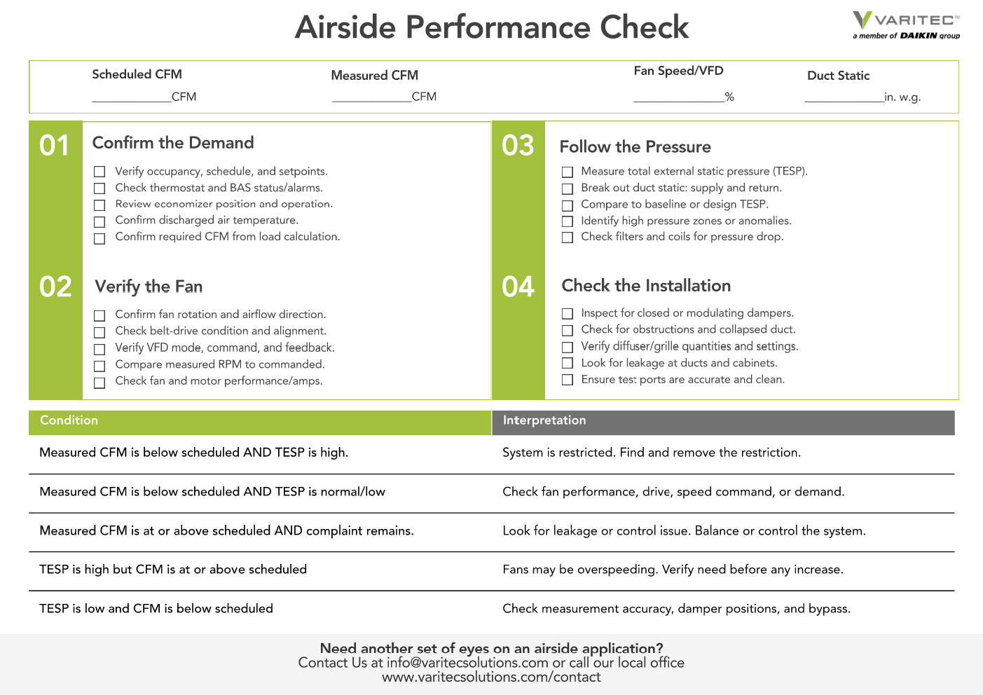
If an AHU is short on airflow, the fan is only one part of the investigation.
Our Airside Performance Check walks through the measurements and questions worth reviewing before changing fan speed — including coil and filter pressure drop, fan operation, system resistance, static pressure and what the controls are actually asking the system to do.

Variable-speed capability changes how a fan can respond to the system, but VFD and ECM approaches aren’t identical.
Our VFD vs. ECM Comparison provides a side-by-side look at the differences to consider when evaluating the right approach for an application.