
Every air handling unit is the result of hundreds of design decisions.
Fan selection.
Coil selection.
Cabinet construction.
Damper performance.
Controls integration.
Service access.
Each decision influences the performance of the others.
The challenge is that buildings don’t operate one component at a time—they operate as complete airside systems. Understanding how those individual design decisions affect overall system performance is fundamental to effective airside optimization.
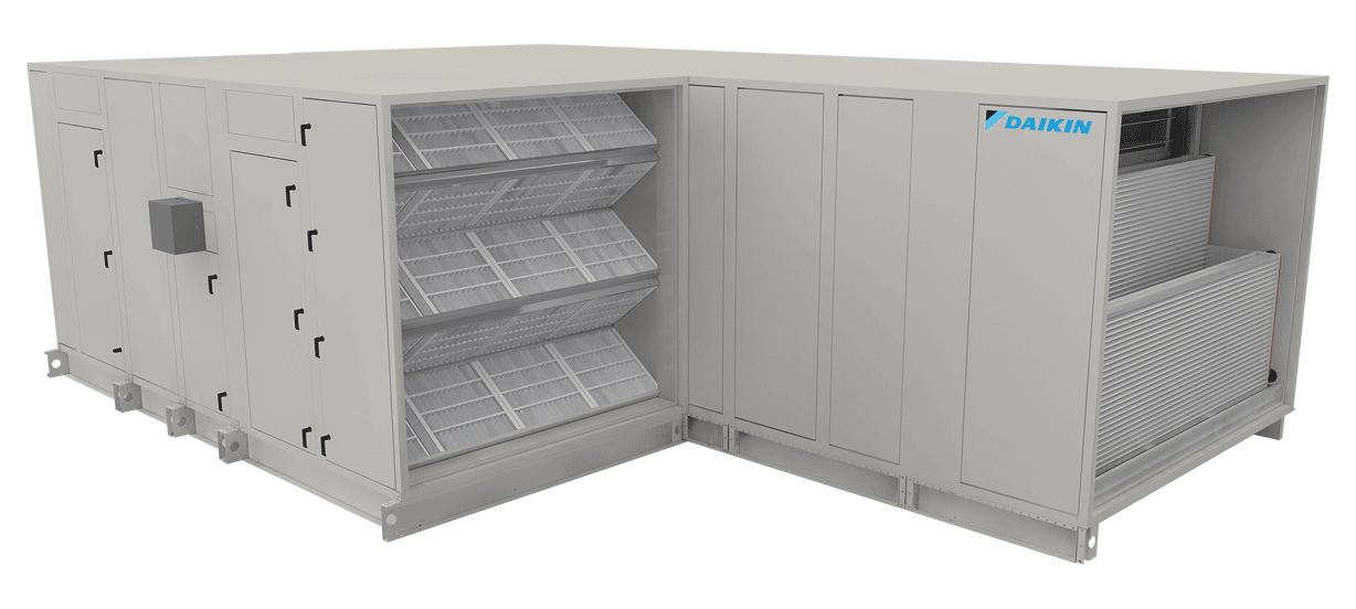
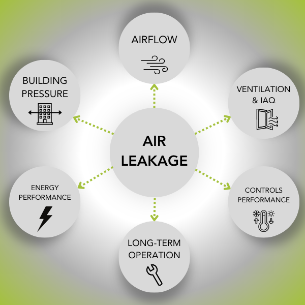
Air leakage is one of the clearest examples of why systems perspective matters. It’s often viewed as a specification buried within an equipment submittal: a cabinet leakage rating, a damper leakage class, or a performance percentage reported during testing. In reality, leakage can influence airflow, building pressure, ventilation, humidity control, controls performance, and energy consumption throughout the life of the system.
The amount of leakage matters, but so does where it occurs and how it affects overall system performance.
The sections that follow examine where air leakage occurs, how it influences overall system performance, and how a systems-thinking approach helps engineers evaluate its impact within the complete airside system.
Unlike a failed fan or a clogged filter, air leakage rarely presents itself as a single, obvious problem. Instead, it often appears as a collection of symptoms that seem unrelated—or point to the wrong cause.
A building may struggle to maintain positive pressure. Outdoor air percentages may drift. Space humidity becomes difficult to control. Occupants report comfort complaints even though the equipment appears to be operating normally.
Because these issues span multiple disciplines, each team may verify that its portion of the system is functioning as intended. The mechanical contractor confirms equipment operation. The controls contractor verifies the sequence of operation. TAB confirms airflow. Commissioning validates system functionality.
As a result, air leakage can remain hidden even when individual components appear to be operating as designed.
Air leakage isn’t simply an equipment specification. It’s a system-performance consideration because its effects can extend well beyond the location of the leak.
To understand those impacts, it helps to first understand where air leakage commonly occurs.
Not all air leakage has the same impact. Two systems may have similar leakage rates but experience very different operating consequences depending on where the leakage occurs and the pressure conditions within the air handling unit.
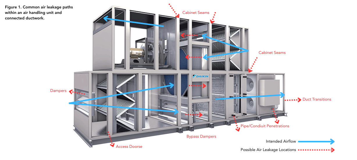
Figure 1 highlights the most common leakage paths found within an air handling unit and connected ductwork. Cabinet seams, access doors, dampers, pipe penetrations, field-assembled sections, and duct transitions all have the potential to become unintended leakage paths. While manufacturers evaluate cabinet leakage using standards such as AHRI 1350 and damper leakage using AMCA 500-D, these ratings represent controlled laboratory conditions. Installation quality, commissioning, maintenance, and operating conditions all influence how the system performs in the field.
Cabinet leakage is only one source. Dampers, ductwork, access doors, and field installation details can all influence overall airside performance and should be considered as part of the complete system.
The location of a leak often matters as much as the amount of air leaking.
Leaks on the negative-pressure side of the fan allow unconditioned air to enter the system, increasing the amount of air that must be heated, cooled, filtered, humidified, or dehumidified. Leaks on the positive-pressure side allow conditioned air to escape before it reaches the occupied space, reducing delivered airflow and affecting ventilation and building pressure.
Rather than evaluating leakage by specification alone, it should be considered how leakage paths influence the performance of the entire airside system.
The effects of air leakage extend beyond the air handling unit itself. Depending on where leakage occurs and how the system operates, it can influence multiple aspects of HVAC performance.
Application | Why Leakage Matters |
| Commercial Offices | Energy efficiency, occupant comfort, and maintaining outdoor-air ventilation. |
| Healthcare | Maintaining pressure relationships, ventilation requirements, and humidity control in critical spaces. |
| Laboratories | Supporting directional airflow and pressurization required for occupant safety and process integrity. |
| Education | Providing consistent ventilation, occupant comfort, and efficient operation across varying occupancy schedules. |
| Industrial & Manufacturing | Maintaining process conditions, ventilation effectiveness, and building pressure where operations are sensitive to airflow. |
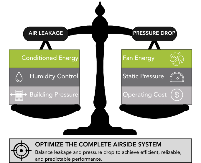
Air leakage and pressure drop are separate performance characteristics, but they are often evaluated together during equipment and damper selection.
Air leakage is airflow passing through or around a component where it is not intended.
Pressure drop is the resistance imposed on the intended airflow as it moves through a component.
Design decisions such as casing construction, seals, damper blades, transitions, and other airside components may influence both characteristics. However, a low-leakage product is not inherently a high-pressure-drop product, nor is a low-pressure-drop product inherently leaky. Each characteristic should be evaluated independently using standardized performance data.
This distinction is reflected in industry standards. AMCA 500-D provides separate test methods for damper leakage and pressure drop, while AHRI 1350/1351 separately evaluates AHU casing leakage and other mechanical performance characteristics.
Although air leakage and pressure drop are evaluated independently, they influence energy consumption in different ways.
Pressure drop affects all of the intended airflow moving through the system whenever the fan operates. Even a modest increase in pressure drop can increase fan energy because the fan must overcome that additional resistance across the system’s full design airflow for every operating hour.
The energy associated with air leakage depends on several factors, including:
Depending on the application, air leakage may result in:
Effective airside optimization requires considering both leakage and pressure drop together rather than attempting to minimize either characteristic in isolation.
A good example is damper selection. In the Southwest, economizers can provide significant hours of free cooling because of cool nighttime temperatures and large daily temperature swings. Capturing those energy savings depends on more than simply opening the outdoor air damper. Low-leakage dampers help maintain intended airflow, building pressurization, and ventilation performance, while pressure drop directly affects fan energy consumption. Focusing on only one characteristic can improve one aspect of system performance while negatively affecting another.
The lowest leakage rate is not always the best solution.
The right balance delivers the best overall system performance.
While every project has different priorities, a few design principles can help ensure air leakage is evaluated as part of the complete airside system—not simply as an equipment specification.
Mechanical and controls design should work together to achieve the intended system performance. Economizer sequences, building pressurization strategies, and airflow control all rely on components operating as expected. Even well-designed sequences cannot overcome mechanical limitations such as excessive leakage or improperly selected dampers.
The appropriate leakage performance depends on the building, occupancy, and operating requirements. A healthcare isolation room, research laboratory, and commercial office may all justify different design decisions based on their ventilation, pressurization, and humidity requirements.
Even the best design should be easy to verify. Providing access for inspection, testing, balancing, and commissioning makes it easier to confirm that the system is performing as intended—not just during startup, but throughout its operating life.
Air leakage performance isn’t determined on the day the equipment is installed. Maintenance, adjustments, component replacement, and years of operation can all influence how the system performs over time. Designing with long-term operation in mind helps preserve performance throughout the building’s lifecycle.
When system performance doesn’t match the design intent, air leakage is often overlooked because its effects appear elsewhere. Building pressure may fluctuate, ventilation rates may drift, humidity may become difficult to control, or the BAS may require repeated adjustment—even though the root cause lies outside the control sequence.
A systematic approach can help determine whether unintended leakage is contributing to the problem.
Begin by understanding the pressure zones within the air distribution system. Leaks on the negative-pressure side allow unconditioned air to enter the system, while leaks on the positive-pressure side allow conditioned air to escape before it reaches the occupied space. Knowing where the system is under positive or negative pressure helps narrow the search and connect observed symptoms to potential leakage paths.
Before adjusting control sequences, confirm that the mechanical system is operating as intended. Inspect cabinet seams, access doors, duct connections, and penetrations for visible leakage. For dampers, verify blade position, actuator travel, linkage adjustment, end stops, and seals.
Remember, a BAS command of 0% confirms what the controller requested—it doesn’t confirm that the damper is fully closed.
Verification methods should match the application and the suspected leakage path. Smoke pencils, ultrasonic leak detection, airflow measurements, and TAB testing can all help identify suspected leakage or confirm system performance.
When a more quantitative evaluation is required, ASHRAE Standard 215 provides a standardized method for measuring and reporting leakage airflow in operating HVAC air distribution systems, giving engineers a consistent approach for evaluating field performance.
Whether using field observations or standardized testing, the objective remains the same: determine how unintended air leakage influences the performance of the complete airside system.
Safety Note: Any smoke or fog testing should be coordinated with the equipment manufacturer, facility personnel, and fire alarm team before testing begins.
A closed command confirms what the controls requested—not necessarily what the damper did.
Verifying mechanical movement is just as important as verifying the sequence of operation.
Air leakage is often reduced to a cabinet rating or damper specification, but its influence extends well beyond a single published value. Its impact depends on where leakage occurs, how the system operates, and how it interacts with airflow, ventilation, controls, humidity, and building pressure.
Evaluating air leakage therefore requires more than comparing specifications. It requires understanding how individual design decisions work together to influence the performance of the complete airside system—from equipment selection and installation through commissioning and long-term operation.
The goal isn’t simply to specify the lowest leakage rate. It’s to design an airside system in which every component works together to deliver reliable, efficient, and predictable performance.